
Why Memory Hierarchy Matters in AI Accelerators
Modern AI accelerators are not limited by compute power.They are limited by data movement.You can design a GPU capable of petaflops of compute. You can pack thousands of tensor cores onto a single die. But if those cores can’t access data fast enough, they sit idle.
And idle compute is wasted silicon.This imbalance between compute throughput and memory bandwidth is the defining challenge of modern AI hardware. It’s often described as the AI memory bottleneck, where FLOPS scale faster than memory systems can feed them.
Let’s unpack why hierarchy exists at all.
FLOPS vs Bandwidth Imbalance
FLOPS measure compute capability. Bandwidth measures data movement capacity.
In modern AI GPUs:
- Compute scales exponentially.
- Memory latency improves slowly.
- Bandwidth scales structurally (via HBM).
If compute doubles but memory bandwidth doesn’t, utilization drops. Tensor cores stall waiting for operands.
This is compute starvation.
Latency Tiers in Modern GPUs
Not all memory is equal.
Registers operate in single-digit nanoseconds.
L1 cache slightly slower.
L2 cache slower still.
HBM much larger but slower than SRAM.
Each tier exists because physics prevents one memory type from being:
- Extremely fast
- Extremely large
- Extremely energy efficient
All at once.
So designers layer memory into a hierarchy.
Tensor Streaming Behavior
AI training is not random memory access. It is structured tensor streaming.
Weights move in blocks.
Activations flow layer by layer.
Gradients propagate backward.
This structured flow benefits from:
- Data locality
- Reuse inside caches
- High-bandwidth staging from HBM
Without hierarchy, every tensor fetch would go directly to large off-chip memory killing performance.
Compute Starvation Problem
Imagine a restaurant kitchen with world-class chefs but only one waiter bringing ingredients.
That’s a GPU without hierarchy.
Memory hierarchy solves this by:
- Keeping frequently used data close to compute
- Using large bandwidth pools for bulk transfer
- Minimizing expensive long-distance data movement
Hierarchy isn’t optional.
It is architectural survival.
Overview of AI Memory Hierarchy Layers
Before diving deeper, let’s zoom out and see the entire structure at once.
AI accelerator memory isn’t flat. It’s layered like a pyramid. The closer the memory sits to the compute unit, the faster it is. The farther away it is physically, the larger it becomes but with higher latency.
Here’s the simplified tier model:
Top (Fastest, Smallest, Closest to Compute)
→ Registers
→ Shared Memory
→ L1 Cache
→ L2 Cache
Bottom (Largest, Highest Bandwidth, Off-Chip)
→ HBM (High Bandwidth Memory)
Each layer serves a specific purpose.
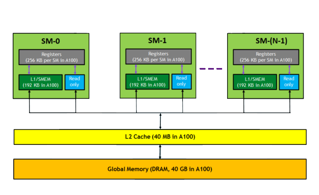
Registers (Fastest, Smallest)
Registers sit directly inside tensor cores or CUDA cores. They store operands actively being computed. Access latency is extremely low — often just a few clock cycles.
But capacity?
Tiny.
We’re talking kilobytes per core.Registers exist for immediate arithmetic operations. Nothing more.
Shared Memory
Shared memory is on-chip SRAM that allows threads within a block to reuse data efficiently. It dramatically reduces redundant trips to higher memory tiers.
Shared memory is programmer-visible in GPU programming models.
It’s like a local scratchpad.
L1 Cache
L1 cache automatically stores recently accessed data close to compute units. It improves temporal locality meaning if data was accessed recently, it’s likely to be accessed again.
Latency is very low.
Capacity is limited.
L2 Cache
L2 cache is larger and shared across streaming multiprocessors. It acts as a buffer between on-chip SRAM and off-chip HBM.
It reduces HBM traffic significantly.
HBM (Largest, Massive Bandwidth)
HBM sits off-chip but on-package. It provides terabytes-per-second bandwidth. It is slower than SRAM but dramatically larger in capacity.
It’s the bulk storage layer for:
- Model parameters
- Activations
- Gradients
AI Accelerator Memory Hierarchy (Conceptual)
- Capacity increases
- Latency increases
- Bandwidth characteristics change
- Energy per access increases
As you move downward:
This hierarchy exists because building 100 GB of register-speed memory is physically impossible.
Tradeoffs define architecture.
On-Chip Memory (SRAM-Based Architecture)
Everything above HBM is built using SRAM — static random-access memory.
SRAM is:
- Extremely fast
- Low latency
- Very power efficient per access
- Very expensive in silicon area
This is why SRAM capacity is limited.
Registers in Tensor Cores
Registers hold operands for matrix multiplications inside tensor cores. During AI training:
- Matrix tiles are loaded
- Stored in registers
- Processed
- Accumulated
Registers are the final staging area before arithmetic.
Latency: ~1–2 cycles
Capacity: Extremely small
They are not designed for storage. They are designed for execution.
Shared Memory Blocks
Shared memory allows cooperative data sharing among threads.
Example:
If multiple threads need the same weight tile, instead of fetching from HBM multiple times:
- Fetch once into shared memory
- All threads reuse it
This reduces:
- HBM bandwidth pressure
- Energy consumption
- Latency
Shared memory is explicitly managed in many AI kernels.
L1 Cache Role
L1 cache stores recently used instructions and data.
Its goal is to:
- Capture temporal locality
- Reduce repeated trips to L2
Latency: Very low
Size: Larger than registers, smaller than L2
L2 Cache in Modern GPUs
L2 cache acts as a shared buffer across compute blocks.Modern AI GPUs have multi-megabyte L2 caches sometimes tens of megabytes.
It:
- Reduces HBM traffic
- Buffers tensor chunks
- Improves bandwidth efficiency
Without L2, every data reuse event would hit HBM overwhelming off-chip bandwidth.
Latency Differences Across SRAM Levels
Registers < Shared Memory < L1 < L2 < HBM
Each jump downward increases access time slightly.
But moving up increases area cost dramatically.
Physics forces this design.
Data Reuse Optimization
AI workloads are ideal for cache hierarchy because:
- Matrix operations reuse blocks
- Convolution layers reuse kernels
- Transformer attention layers reuse query/key/value matrices
Memory hierarchy exploits this reuse.
Without it, even HBM’s multi-terabyte bandwidth wouldn’t be enough.
Off-Chip High Bandwidth Memory (HBM Layer)
Now we reach the bottom of the hierarchy.HBM is not on-chip SRAM.It is stacked DRAM placed on-package.
Why external?
Because SRAM cannot scale to hundreds of gigabytes without becoming economically impossible.HBM solves capacity + bandwidth at scale.
- 3D stacked DRAM dies
- TSV vertical interconnects
- 1024-bit wide interface
- Silicon interposers
This architecture enables:
3–5 TB/s bandwidth in modern GPUs.
HBM stores:
- Full model weights
- Layer activations
- Optimizer states
- Gradients
But HBM is slower than SRAM.
So data flows upward:
HBM → L2 → L1 → Registers
This staging prevents frequent expensive off-chip access.HBM is bulk storage.SRAM is execution memory.
To understand how wide-bus stacking enables massive throughput, read our Complete HBM architecture explained guide.
Data Flow During AI Training
Now let’s walk through what actually happens when you train a large language model.Forget theory for a second.Imagine a forward pass in a transformer layer. Billions of parameters sit inside HBM. Tensor cores are waiting for matrix multiplications. How does data physically move?
Modern GPUs such as those based on the NVIDIA Hopper architecture implement advanced memory hierarchies that tightly integrate registers, shared memory, L2 cache, and HBM to maximize tensor throughput.
Here’s the step-by-step memory journey:
Step 1: Parameters Stored in HBM
All model weights often tens or hundreds of gigabytes reside in HBM. This is the bulk storage layer.
HBM provides massive bandwidth (3–5 TB/s), but it is still slower than on-chip SRAM. So data does not stay in registers permanently. It must be staged.
Step 2: HBM → L2 Cache
When a layer begins execution, required tensor blocks are fetched from HBM into L2 cache.L2 acts as a high-capacity buffer.
Why not go directly to L1?
Because L2 is shared across compute blocks and helps reduce repeated HBM fetches. If multiple streaming multiprocessors need the same data, L2 serves as a reuse hub.
Step 3: L2 → L1 Cache
From L2, smaller chunks are pulled into L1 cache. L1 is closer to compute and optimized for lower latency.
This stage improves:
- Temporal locality
- Instruction reuse
- Data block efficiency
Step 4: L1 → Registers
Now we’re at execution level.Registers hold operands directly used by tensor cores. This is where matrix multiply-accumulate operations happen.Latency here is minimal just a few clock cycles.
Step 5: Compute Execution
Tensor cores perform:
Matrix multiply
Accumulation
Activation application
All using register-resident operands.
Step 6: Writeback Cycle
After compute:
- Partial sums may return to registers
- Final outputs move back to L1
- Then to L2
- Eventually written back to HBM
This cycle repeats layer after layer.
Tensor Streaming Cycle
During training:
Forward pass → Activations stored
Backward pass → Gradients computed
Optimizer step → Weights updated
Each stage requires massive data movement between tiers.Without hierarchy, every read and write would hit HBM directly.Bandwidth would collapse.This entire flow exists to minimize expensive long-distance data travel.
Latency vs Bandwidth Across Memory Tiers
Now let’s compare tiers side-by-side.
| Memory Type | Latency | Bandwidth | Capacity |
|---|---|---|---|
| Registers | Lowest | High (local) | Very Small |
| L1 Cache | Very Low | High | Small |
| L2 Cache | Low | Medium–High | Medium |
| HBM | Higher | Extremely High | Large |
Notice something interesting.
HBM has higher latency than SRAM, but dramatically higher aggregate bandwidth.
That’s why hierarchy exists.
If everything were registers:
- Latency = amazing
- Capacity = impossible
- Cost = catastrophic
If everything were HBM:
- Capacity = great
- Bandwidth = strong
- Latency = too slow for execution
So designers combine both.
Hierarchy balances:
Speed
Size
Energy
Cost
It is not a design choice.It is a physical necessity.
Memory Hierarchy Optimization in LLM Training
Large language models amplify every inefficiency in memory design.
Let’s see how hierarchy is optimized specifically for LLMs.
Parameter Streaming
During training, model parameters are streamed layer-by-layer from HBM into caches.
Efficient scheduling ensures:
- Maximum cache reuse
- Minimal redundant fetches
- Predictable memory access patterns
This keeps HBM saturated but not overloaded.
Gradient Accumulation
Gradients are accumulated in registers and shared memory before being written back to HBM.
This reduces:
- Write amplification
- Energy cost
- Bandwidth pressure
Instead of writing partial gradients repeatedly, they’re combined locally first.
Activation Checkpointing
To reduce memory footprint, some activations are recomputed instead of stored.
This is a compute-for-memory tradeoff.
Hierarchy makes this viable because:
- Recomputed values can stay in SRAM
- Only essential data is written to HBM
Data Locality Optimization
AI kernels are designed to:
- Tile matrices
- Reuse blocks
- Keep hot data in L1/L2
The goal is simple:
Minimize trips to HBM.Because even though HBM has massive bandwidth, it still consumes more energy per access than SRAM.
Energy Efficiency Across Memory Levels
Here’s something most people underestimate:
Data movement often consumes more energy than arithmetic.
Yes.Moving data costs more than multiplying it.
SRAM Power Per Access
SRAM (registers, caches):
- Very low latency
- Very low energy per access
- Very high area cost
Accessing registers is extremely efficient.
HBM Power Per Bit
HBM is optimized for bandwidth per watt, but:
- Off-chip signaling consumes more energy
- TSVs reduce trace distance but still cost more than on-chip access
This is why minimizing HBM traffic is critical.
As explained in the AI Infrastructure Memory Energy Costs analysis, large-scale AI clusters spend enormous power budgets just moving data between memory tiers.
Data Movement Dominates Energy
In large AI training jobs:
- Arithmetic energy = significant
- Data movement energy = dominant
The further data travels, the more it costs.
Memory hierarchy exists to reduce that distance.
Registers → lowest cost
HBM → higher cost
Energy-aware scheduling is now as important as compute optimization.
Future of AI Memory Hierarchy
Memory hierarchy is evolving because AI is evolving.
The pressure is relentless.
On-Package SRAM Scaling
Designers are increasing:
- L2 cache size
- On-chip buffer capacity
- Shared memory configurability
More SRAM reduces HBM dependency.But SRAM area is expensive.
So tradeoffs remain.
Hybrid Bonding
Hybrid bonding reduces interconnect resistance and increases density between dies.
This may enable:
- Tighter integration of memory and compute
- Lower latency off-chip access
- Higher bandwidth per watt
HBM evolution depends heavily on packaging innovation.
Compute + Memory Integration
Future accelerators may blur the boundary between:
Compute
Memory
In-memory compute architectures could reduce data movement dramatically.
Instead of moving tensors to compute units, compute logic may move closer to memory arrays.
Toward Memory-Centric AI Architecture
Historically, systems were compute-centric.Now they are becoming memory-centric.Because scaling compute without scaling memory hierarchy leads back to the memory wall the exact constraint detailed in the AI Memory Bottleneck discussion.
The future of AI hardware will not be defined by:
How many FLOPS you can build.
But by:
How efficiently you can move data.Memory hierarchy is no longer background infrastructure.It is the central design challenge of AI acceleration.
FAQs
Why do AI accelerators use multiple memory layers instead of a single large memory?
AI accelerators use a layered memory hierarchy because no single memory type can deliver ultra-low latency, massive capacity, high bandwidth, and energy efficiency simultaneously. Registers and SRAM caches provide fast access for active computation, while HBM offers large-capacity, high-bandwidth storage. This tiered design prevents compute starvation and optimizes performance.
What is the difference between SRAM and HBM in AI GPUs?
SRAM (used for registers and caches) is extremely fast and low-latency but limited in size and expensive in silicon area. HBM (High Bandwidth Memory) is larger and provides massive bandwidth (3–5 TB/s), but it has higher latency compared to SRAM. SRAM handles immediate execution data, while HBM stores bulk model parameters and activations.
How does data flow during AI model training?
During AI training, data typically flows from HBM to L2 cache, then to L1 cache, into registers for tensor computation, and finally back to HBM for storage. This staged movement minimizes expensive off-chip memory access and ensures high GPU utilization.
What happens if memory bandwidth is insufficient in AI accelerators?
If memory bandwidth cannot keep up with compute throughput, tensor cores stall while waiting for data. This is known as the memory bottleneck problem. Insufficient bandwidth reduces FLOPS utilization and increases training time significantly.
Why is HBM placed off-chip instead of on-chip?
HBM is placed off-chip because integrating hundreds of gigabytes of SRAM directly on-chip would be physically impractical and economically unfeasible. HBM uses 3D-stacked DRAM architecture to provide high capacity and wide bandwidth while remaining close to the GPU via silicon interposers.
Conclusion
AI accelerators are not just massive compute engines; they are carefully layered memory systems designed to prevent starvation. Registers execute, caches buffer, and HBM feeds the system in a tightly coordinated hierarchy. During AI training, data flows continuously across tiers from HBM to L2, then to L1, into registers for computation, and eventually back to HBM for storage.
Each layer exists because no single memory technology can deliver ultra-low latency, massive capacity, extreme bandwidth, and perfect energy efficiency all at once. Memory hierarchy balances these tradeoffs by keeping frequently accessed data close to compute while using high-bandwidth memory for large-scale storage.
As models scale from billions to trillions of parameters, the importance of hierarchy becomes even more critical. Energy economics, latency optimization, and bandwidth scaling converge into one architectural reality: AI performance is limited not by compute alone, but by how intelligently memory is structured. In modern accelerators, memory hierarchy is the true backbone of AI scalability.